Design of a Radio Telescope
 (Foundations
of Astronomy, 6th Edition)
(Foundations
of Astronomy, 6th Edition)
Radio
telescopes are not always constructed in the same exact way. There can be variations of the antennas and
receivers. The following describes a
typical radio telescope.
A
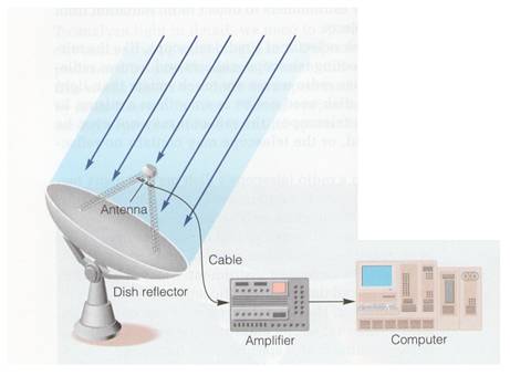
radio telescope can be divided into 4 functional parts. The four parts are: the reflector dish, the
antenna, the amplifier and the receiver/recorder. The large dish that most people associate
with a radio telescope is used to focus the radio waves. Since radio waves are much longer than
visible light waves, the dish of the radio telescope does not need to be
perfectly smooth, like the ground mirrors of a reflecting telescope. In fact,
some radio telescopes use a wire mesh as the reflecting dish. It will still be able to deflect the long
waves to a detection device.
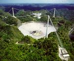
The
radio telescope reflector pictured above is able to be moved at the base to
point to an area of interest in the sky.
It has an alt-azimuth drive, a motorized device that allows movement up
and down and side to side. Some radio telescopes such as
The
antenna of the radio telescope is at the center of the dish, and perched above
it. The waves that are reflected by the
dish are directed at the antenna. The antenna absorbs radio energy and the
signal is carried by a cable to an amplifying device, to strengthen the signal.
After preamplification, the signal is carried to a building which houses the
receiver. The receiver further amplifies
the signal and the signal is integrated and may be recorded on an analog
recorder, usually pen on moving chart paper.
The signal is then transmitted to a computer which will record the signal
in digital form and the data can then be further processed if desired. Oftentimes,
the data is converted into a contour map.
The contour map shows areas of higher and lower densities of radio
waves. This representation can be
manipulated to show colors or shading which is of course not actually visible
to the human eye. The contour map gives
us a picture that we can understand easily of where matter is found in between
stars.
Improving
the Signal
Radio
signals received by radio telescopes are rather weak. A large reflector dish such as the one
constructed at
Radio
signals can be improved by using more than one radio telescope in a
system. By adding the signals from radio
telescopes together, the resolving power can be improved. When radio telescopes are linked in this way,
it is called a radio interferometer. The
Very Large Array (VLA) located in
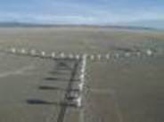
Very
Large Array (NRAO/ AUI/ NSF)